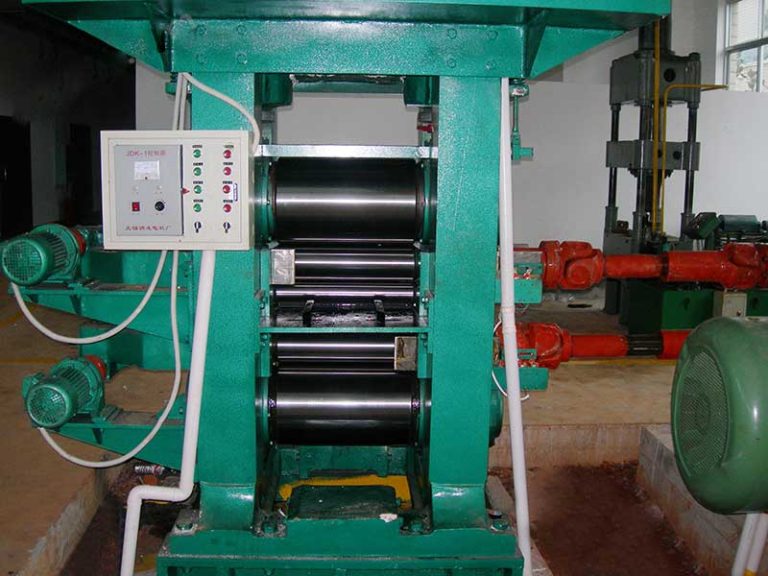
Importance of Cold Rolling Mill Production Capacity Calculation and Roll Material Selection Requirements
Cold Rolling Technology & Process Engineering
In modern steel and non‑ferrous strip production, the cold rolling mill is the core piece of equipment that determines product quality, delivery reliability and overall production cost. For process engineers, plant managers and equipment buyers, two topics are especially critical:
- Accurate calculation of cold rolling mill production capacity
- Scientific selection of work roll and backup roll materials
This technical guide explains how to estimate realistic capacity for 4‑high, 6‑high and multi‑roll mills, and how to choose suitable roll materials for carbon steel, stainless steel, copper and aluminum cold rolling applications. Numerical examples and reference data are included for practical production planning and mill design.
1. Why Capacity Calculation Matters in Cold Rolling Mills
In many plants, nominal design capacity of the cold rolling mill (e.g. “800,000 t/year”) is quite different from the actual achievable capacity. Over‑estimating capacity leads to:
- Unrealistic delivery commitments
- Frequent schedule changes and overtime
- Higher inventory and logistic costs
Under‑estimating capacity, on the other hand, causes:
- Under‑utilization of expensive cold rolling equipment
- Incorrect investment decisions for new mills
- Higher fixed cost per ton due to low throughput
Therefore, a realistic capacity calculation, based on actual rolling speeds, yield, downtime and strip mix, is essential for process optimization, energy balance and long‑term strategic planning of cold rolling operations.
2. Basic Concepts of Cold Rolling Mill Capacity
For a typical tandem cold rolling mill (for example, a 5‑stand 4‑high continuous mill), different types of “capacity” are used in engineering calculations:
- Theoretical capacity – based on maximum strip speed and 100% equipment availability
- Technical capacity – includes typical downtime for roll changes, maintenance and grade changes
- Commercial (effective) capacity – further reduced by order mix, coil size, operator skill and plant organization
For practical production management, the commercial capacity is the most meaningful metric. It is normally expressed in tons per year (t/a) or million tons per year (Mt/a) for a specific cold rolling mill configuration.
3. Core Formula for Cold Rolling Mill Production Capacity
A basic continuous cold rolling mill capacity can be estimated using the following idealized formula:
Where:
- Qth – theoretical capacity, kg/h
- Vavg – average strip speed at mill exit, m/s
- Beff – effective strip width (net width, minus edge trimming), m
- tout,avg – average exit strip thickness, m
- ρ – density of metal (e.g. 7,850 kg/m³ for carbon steel, 8,000 kg/m³ for stainless, 2,700 kg/m³ for aluminum)
To obtain annual capacity Qyear, consider effective operating time and various efficiency factors:
Where:
- Hyear – calendar hours per year (usually 8,000–8,400 h)
- ηtime – time efficiency (availability) considering planned and unplanned downtime
- ηutil – utilization factor, considering coil change, threading, acceleration and deceleration
- ηyield – yield factor, considering head/tail scrap, edge trimming and quality downgrades
For a well‑managed modern cold rolling mill, ηtime is often 0.85–0.92, ηutil 0.70–0.85, and ηyield 0.93–0.97, depending on product mix and automation level.
3.1 Example Calculation for a 5‑Stand Tandem Cold Rolling Mill
Consider a carbon steel 5‑stand tandem cold rolling mill line processing low‑carbon steel strip from 2.0 mm down to 0.3–0.5 mm. Typical parameters:
- Exit thickness tout,avg = 0.35 mm = 0.00035 m
- Net strip width Beff = 1,250 mm = 1.25 m
- Average exit speed Vavg = 14 m/s (≈ 840 m/min)
- Density ρ = 7,850 kg/m³
Theoretical capacity:
Assuming:
- Hyear = 8,400 h/a
- ηtime = 0.88
- ηutil = 0.78
- ηyield = 0.96
This value is consistent with many industrial tandem cold rolling mills designed for around 0.8–1.0 Mt/a capacity for standard low‑carbon steel strip.
3.2 Reference Capacity Range for Typical Cold Rolling Mills
| Mill Type | Configuration | Typical Strip Width (mm) | Exit Thickness Range (mm) | Max Exit Speed (m/min) | Practical Capacity (t/a) |
|---|---|---|---|---|---|
| Reversing cold rolling mill | 4‑high, single stand | 800–1,600 | 0.3–2.5 | 600–1,000 | 150,000–350,000 |
| Tandem cold rolling mill | 4‑high, 4–5 stands | 900–1,850 | 0.15–2.0 | 1,400–2,200 | 700,000–1,800,000 |
| 6‑high reversible mill (HC / UCM) | 6‑high, single stand | 850–1,650 | 0.12–1.8 | 800–1,200 | 250,000–450,000 |
| 20‑roll mill (Sendzimir type) | Cluster, reversible | 200–1,250 | 0.02–1.0 | 200–800 | 50,000–180,000 |
| Aluminum cold rolling mill | 4‑high or 6‑high, single or tandem | 1,000–2,050 | 0.08–3.0 | 1,200–2,000 | 200,000–600,000 |
Note: Capacity ranges are indicative and depend strongly on product mix, thickness range, steel grades and operating practices.
4. Key Parameters Influencing Cold Rolling Mill Capacity
Even when the mill mechanical design is fixed, several process and operational factors have a large impact on effective capacity:
4.1 Strip Thickness and Draft Schedule
For a given motor power and strip width, exit speed is generally limited by rolling load, strip flatness and stand torque. Thinner exit gauge and higher total reductions mean:
- Higher specific rolling force (kN/mm)
- Higher power consumption per ton
- Lower achievable speed for heavy‑gauge or high‑strength grades
Optimized draft patterns over 4–6 stands can significantly increase mill throughput, especially for mixed products with both heavy and light gauges.
4.2 Steel Grade and Strip Hardness
Low‑carbon mild steel, high‑strength low‑alloy steel (HSLA), dual‑phase steel and stainless steel require different reductions and rolling forces. For instance, typical yield strength levels:
- Mild carbon steel: 180–280 MPa
- HSLA: 350–600 MPa
- Advanced high‑strength steels (AHSS): 600–1,200 MPa
- Austenitic stainless steel (e.g. 304): 210–310 MPa but strong work hardening
Higher strength or work‑hardening grades reduce rolling speed and overall capacity because of roll force and motor limits. That is why cold rolling mills dedicated to automotive AHSS often have a lower commercial capacity compared to mills rolling only mild steel.
4.3 Coil Logistics, Coil Weight and Coil Build‑up
Mill stoppages for coil change, re‑threading and head‑end cutting consume significant time. Higher average coil weight reduces these losses. In many steel plants, switching from 15‑ton to 25‑ton coils increased cold mill throughput by 5–10% without major equipment changes.
Practical strategies to improve effective capacity include:
- Optimized coil scheduling to reduce thickness and grade changes
- Use of welding and no‑threading “endless” rolling in acid pickling & tandem cold rolling (PL‑TCM)
- Well‑designed entry/exit coil handling to minimize waiting time
4.4 Mill Downtime and Maintenance Strategy
As a rule of thumb, every 1% improvement in time availability of a large tandem cold rolling mill often corresponds to 7,000–12,000 t/a additional capacity, depending on mill size. Correct spare parts planning, predictive maintenance (vibration and oil analysis) and systematic roll shop management help to increase the time efficiency factor ηtime.
4.5 Automation and Thickness Control
Advanced automatic gauge control (AGC), automatic flatness control (AFC), model‑based setup calculation and coil‑to‑coil learning systems allow:
- Faster acceleration to target speed
- Reduced scrap due to out‑of‑tolerance gauge and flatness
- Better control of rolling force between stands
All of these factors contribute to a higher effective strip speed and improved yield factor ηyield.
5. Practical Capacity Calculation Workflow for a Cold Rolling Mill
To create a realistic capacity model for an existing or planned cold rolling mill, the following step‑by‑step method is commonly used in process engineering:
- Define product range – thickness, width, grades, target tonnage for each group.
- Determine typical rolling speeds – from historical data or mill design, for each product group.
- Calculate theoretical strip throughput – using the core formula for each product.
- Estimate time distribution – rolling time, coil change time, threading time, maintenance shutdowns.
- Determine efficiency factors – derive ηtime, ηutil, ηyield from historical KPIs.
- Aggregate for yearly capacity – include planned mix of products, new grade introductions and seasonal patterns.
- Run sensitivity analysis – evaluate impact of speed increase, coil weight increase or reduced downtime.
This quantitative approach enables mill operators to justify investments (e.g. a new coiler, improved roll coolant system, automation upgrades) based on the additional tonnage achievable per year.
6. Roll Material Selection Requirements in Cold Rolling Mills
The work rolls and backup rolls of a cold rolling mill directly influence strip surface quality, gauge control, flatness and, ultimately, mill capacity. Inadequate roll material selection leads to:
- Frequent roll spalling and surface defects
- Excessive roll wear and short campaign length
- Strip scratching, chatter marks and thickness deviation
Therefore, roll materials must be selected according to strip material, mill configuration, rolling load and cooling/lubrication conditions. The requirements differ for work rolls and backup rolls.
6.1 General Requirements for Cold Work Roll Materials
For 4‑high and 6‑high cold rolling mills, typical work roll diameters range from 350–700 mm, with barrel length 1,000–2,050 mm. Work rolls must satisfy the following key criteria:
- High surface hardness – usually 80–100 HSD (≈ 60–70 HRC) to resist abrasive wear and surface indentation.
- Good toughness and spalling resistance – to withstand cyclic thermal and mechanical loads.
- Sufficient hardenability – to ensure uniform hardness from surface to core, especially for large diameters.
- High resistance to thermal fatigue – due to cooling and friction at high speeds.
- Good grindability – to reduce roll shop time and ensure tight surface tolerance.
The most widely used work roll materials include forged steel rolls, high‑chrome steel rolls and, in some cases, cemented carbide rolls for extremely thin strip and high‑speed applications.
6.2 Typical Work Roll Materials and Properties
| Roll Material Type | Typical Application | Surface Hardness | Roll Dia. Range (mm) | Key Advantages |
|---|---|---|---|---|
| Forged hardened steel (Cr‑Mo, Cr‑Ni‑Mo) | General carbon steel cold rolling, reversing and tandem mills | 60–68 HRC | 400–700 | Good toughness, relatively low cost, widely used |
| Hi‑Cr steel roll (8–12% Cr) | Stainless steel, silicon steel and high‑strength carbon steel cold rolling | 62–72 HRC | 350–650 | Excellent wear resistance, good anti‑spalling performance |
| High‑speed steel (HSS) roll | High‑speed tandem cold rolling mill finishing stands | 70–80 HRC | 300–500 | High hot‑hardness, long campaign life, reduced roll consumption |
| Carbide composite roll (WC‑Co + steel shaft) | 20‑roll mills for ultra‑thin stainless steel, copper and special alloys | ~1,200–1,500 HV | 60–150 (small work rolls) | Extremely high wear resistance, suitable for ultra‑thin gauges |
Values shown are typical ranges for industrial cold work rolls; actual properties depend on grade and heat treatment.
6.3 Backup Roll Material Selection
Backup rolls in 4‑high and 6‑high cold rolling mills carry most of the separating force but do not contact the strip surface directly. Their primary functions are to:
- Provide stiffness to control strip crown and edge drop
- Distribute roll load to work roll barrel
- Reduce work roll deflection and protect against bending
Typical backup roll diameters range from 800–1,500 mm. A common material choice is high‑strength forged steel with good toughness and contact fatigue resistance. Typical performance targets:
- Hardness 35–55 HRC (depending on design and mill type)
- High fracture toughness to prevent catastrophic failures
- High contact fatigue strength to avoid surface pitting under rolling load
Compared with work rolls, backup rolls are usually softer but require a carefully controlled hardness gradient from surface to core. Improper heat treatment can cause cracking and premature failure under repeated high loads.
6.4 Matching Roll Materials to Strip Materials
The choice of roll material directly depends on the strip material and mill type. The following table summarizes typical combinations used in modern cold rolling operations:
| Strip Material | Mill Type | Typical Work Roll Material | Typical Backup Roll Material |
|---|---|---|---|
| Low‑carbon steel (deep drawing, commercial quality) | 4‑high reversing cold rolling mill or tandem cold rolling mill | Forged steel (Cr‑Mo) or Hi‑Cr steel for finishing stands | Forged steel with 35–45 HRC |
| High‑strength low‑alloy steel (HSLA) | 4‑high or 6‑high tandem cold rolling mill | Hi‑Cr steel or HSS for high load stands | High‑strength forged steel, improved contact fatigue |
| Silicon steel (grain‑oriented, non‑oriented electrical steel) | 6‑high cold rolling mill, 4‑high tandem mill | Hi‑Cr steel rolls with excellent wear resistance | Forged steel backup rolls, controlled hardness profile |
| Stainless steel (austenitic, ferritic) | 20‑roll mill (Sendzimir type), 6‑high cold rolling mill | Carbide or special high‑alloy steel rolls with high hardness | Forged steel backup rolls (cluster back‑up in 20‑roll) |
| Copper and copper alloy strip | 4‑high or 6‑high copper cold rolling mill, 20‑roll mill | Forged steel or carbide work rolls depending on thickness | Forged steel backup rolls |
| Aluminum and aluminum alloy strip | 4‑high or 6‑high aluminum cold rolling mill | Forged steel rolls (lower hardness) or special aluminum rolls | Forged steel backup rolls with lower hardness to avoid indentation |
6.5 Surface Roughness and Texturing of Work Rolls
In cold rolling, roll surface roughness directly determines strip surface roughness, lubrication behavior and pickling performance. For high‑quality automotive sheet and appliance sheet, work rolls are often textured by:
- Shot blasting
- Electro‑discharge texturing (EDT)
- Laser texturing
Typical roughness levels (Ra) for work rolls:
- Bright finish: 0.05–0.15 μm
- Standard commercial: 0.25–0.60 μm
- Deep‑drawing automotive: 0.90–1.50 μm
Maintaining stable roll roughness over the campaign is important to keep stable friction conditions, which in turn influences rolling load, strip shape and capacity.
7. Relationship Between Roll Materials and Mill Capacity
Roll material selection is not only a quality issue but also a capacity issue. Properly chosen rolls can significantly increase effective production capacity in several ways:
- Longer roll campaigns – fewer roll changes per day reduce downtime.
- Stable rolling conditions – stable friction and wear allow higher speeds without risking strip defects.
- Improved shape control – stiffer rolls and better surface reduce risk of chatter and strip breaks.
- Reduced roll consumption – lower roll grinding time and cost per ton of rolled product.
For example, upgrading work rolls in finishing stands of a tandem cold rolling mill from conventional forged steel to high‑speed steel often yields 20–50% longer campaign life and enables a 5–10% increase in rolling speed for demanding products. Over a full year, this can translate into tens of thousands of tons additional capacity.
8. Practical Engineering Example: Cold Rolling Mill Capacity vs. Roll Material
Assume a 4‑stand tandem cold rolling mill dedicated to automotive sheet with the following initial parameters:
- Average strip thickness at exit: 0.6 mm
- Average strip width: 1,400 mm
- Average exit speed: 1,200 m/min (20 m/s)
- Annual operating hours: 8,200 h
- Time efficiency ηtime = 0.86
- Utilization ηutil = 0.74
- Yield ηyield = 0.96
- Work rolls: conventional forged steel
After optimizing roll material (finishing stand upgraded to high‑speed steel rolls) and roll coolant, the mill can safely increase speed to 1,350 m/min and reduce roll change frequency by 20%. The improved parameters are:
- Average exit speed: 1,350 m/min (22.5 m/s)
- Time efficiency ηtime = 0.89
- Utilization ηutil = 0.78
- Yield ηyield = 0.97
Using the capacity formulas, this combination of speed and efficiency improvements could increase practical capacity by approximately 12–18%, depending on the product mix, which is often enough to postpone major capital expenditure for a new cold rolling mill.
9. Long‑Tail Considerations for Cold Rolling Mill Design and Operation
When engineering a new cold rolling mill or upgrading an existing one, attention should also be paid to related sub‑systems and process steps that influence both capacity and suitable roll materials.
9.1 Acid Pickling and Line Coupling
Coupled pickling and tandem cold rolling mill lines (PL‑TCM) allow “endless” or semi‑endless rolling. This greatly reduces threading time and coil change losses, thereby increasing ηutil and ηtime. For such high‑speed operations, work roll materials with excellent thermal fatigue resistance and stable friction behavior are required, such as Hi‑Cr steel or HSS in the finishing stands.
9.2 Skin‑Pass (Temper) Mills and Tension Leveling
After the main cold rolling mill, skin‑pass mills and tension levelers are used to:
- Improve strip flatness and shape
- Adjust mechanical properties (yield point elongation, stretcher strain)
- Impart final surface finish and roughness
Work rolls in skin‑pass mills often have specially textured surfaces (EDT or shot‑blasted), and roll materials must support repeated re‑texturing without cracking or spalling. Correct selection here ensures that the full capacity of the upstream cold rolling mill can be translated into saleable, high‑quality strip.
9.3 Cold Rolling Mill Coolant and Filtration System
Rolling lubricants (emulsions or neat oils) strongly influence friction coefficient, roll wear, strip surface cleanliness and strip temperature. A well‑designed emulsion system with proper filtration and temperature control:
- Reduces roll wear and grinding frequency
- Allows higher rolling speed for a given roll material
- Improves strip surface quality and cleanliness for downstream coating processes
Consequently, the performance of the coolant system and the selection of roll materials must be considered together whenever evaluating cold rolling mill performance.
10. Summary: Integrating Capacity Calculation and Roll Material Selection
For engineers and managers responsible for cold rolling operations, capacity calculation and roll material selection are closely connected tasks rather than isolated activities. To achieve reliable, high‑throughput production:
- Use quantitative, product‑specific capacity models to evaluate actual and potential tonnage of each cold rolling mill line.
- Consider efficiency factors (ηtime, ηutil, ηyield) explicitly when planning production and projects.
- Select work roll and backup roll materials based on strip grade, mill type, rolling load and desired campaign length, not just material cost.
- Pay attention to roll hardness, toughness, surface roughness and texturing method because they influence both quality and capacity.
- Integrate cold rolling mill roll material strategy with upstream pickling, downstream annealing, skin‑pass rolling and surface treatment requirements.
By treating cold rolling mill capacity calculation and roll material selection as part of an integrated process engineering strategy, producers can maximize throughput, improve strip quality and extend equipment life, ensuring competitiveness in demanding flat‑rolled steel and non‑ferrous strip markets.