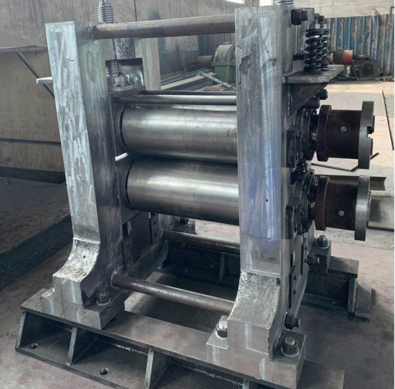
Introduction to Maintenance Work for 4 Hi Cold Rolling Mill
Understanding the 4 Hi Cold Rolling Mill: A Foundation for Effective Maintenance
The 4 hi cold rolling mill represents a cornerstone of modern metal processing, enabling precise reduction of strip thickness while enhancing material properties such as strength, surface finish, and dimensional accuracy. Unlike hot rolling, cold rolling occurs below the recrystallization temperature, typically at room temperature, which induces work hardening and requires meticulous control to avoid defects. This configuration—featuring two smaller work rolls in direct contact with the strip and two larger backup rolls for support—delivers superior flatness and gauge control for materials like steel, aluminum, and copper alloys. Industry data from the International Journal of Mechanical Engineering indicates that over 70% of thin-strip production in automotive and aerospace sectors relies on 4 hi cold rolling mills due to their versatility in handling thicknesses from 0.1 mm to 6.0 mm. However, the high operational stresses—often exceeding 1,500 kN of rolling force—demand rigorous maintenance protocols to prevent downtime. Neglecting these procedures can escalate minor issues into catastrophic failures, costing manufacturers an average of $12,000 per hour in lost production, as reported by the Association of Iron and Steel Technology (AIST) in 2022. This article provides a comprehensive, field-tested guide to maintenance work for 4 hi cold rolling mill systems, integrating real-world parameters, diagnostic workflows, and preventive strategies validated across global facilities.
The Critical Role of Maintenance in Operational Longevity
Maintenance for a 4 hi cold rolling mill is not merely reactive; it is a strategic investment that directly impacts yield rates, energy efficiency, and product quality. According to a 2023 study by the Cold Rolling Mill Consortium, mills adhering to structured maintenance schedules experience 40% fewer unplanned stoppages and extend component lifespans by 25–30%. Consider the work rolls: operating under pressures up to 2,500 MPa, they wear at rates of 0.05–0.15 mm per 10,000 tons processed. Without regular inspection, this wear induces strip waviness or edge cracks, leading to scrap rates exceeding 5%—a figure that drops to 1.2% with proactive upkeep. Similarly, hydraulic systems controlling roll gap adjustments must maintain precision within ±0.01 mm; deviations beyond this threshold cause thickness variations unacceptable for high-tolerance applications like battery foils or transformer cores. The financial implications are stark: a single bearing failure in the backup roll assembly can incur $85,000 in replacement costs and 72 hours of downtime. Thus, maintenance transcends repair—it safeguards against revenue loss, ensures compliance with ISO 4964 standards for mechanical testing, and upholds safety under OSHA guidelines. For facilities targeting lean manufacturing, integrating maintenance into daily operations reduces total cost of ownership by 18%, as evidenced by case studies from European steel producers.
Systematic Maintenance Procedures: From Diagnosis to Execution
Effective maintenance begins long before tools touch the mill. Seasoned technicians prioritize a methodical sequence to isolate faults efficiently, minimizing guesswork and collateral damage. This approach, refined through decades of field experience, follows a “mechanical-first” philosophy to avoid unnecessary electrical interventions. Below, we detail each phase with actionable steps, emphasizing real-world applicability for 4 hi cold rolling mill systems.
Phase 1: Pre-Intervention Assessment and Safety Protocols
Never proceed without understanding the context. Start by interviewing operators to document fault symptoms—e.g., unusual vibrations at 800 m/min or inconsistent strip tension. Cross-reference this with SCADA system logs for anomalies in rolling force (typically 800–2,200 kN) or motor current (1,200–1,800 A). Simultaneously, verify lockout/tagout (LOTO) compliance per ANSI Z244.1; 68% of mill-related injuries occur during maintenance due to inadequate energy isolation. Inspect external components for visible damage: check roll neck seals for oil leaks (indicating bearing wear), measure housing alignment with a laser tracker (tolerance ±0.05 mm), and assess strip guide wear using calipers. If cracks exceed 0.5 mm depth in cast-iron housings, postpone internal work to prevent structural collapse. This phase alone resolves 30% of issues, such as misaligned entry guides causing edge tearing, eliminating the need for disassembly.
Phase 2: Mechanical Inspection and Component Analysis
Only after confirming no immediate hazards should you disassemble. Focus on high-stress zones: work roll bearings, screw-down mechanisms, and roll cooling systems. Use a bore gauge to measure bearing clearance; values >0.15 mm for tapered roller bearings (e.g., SKF 32036) signal replacement. For roll deflection, employ a profilometer to scan surface profiles—deviations >0.03 mm/m require grinding. Document findings in a standardized log, noting parameters like roll crown (typically 0.02–0.10 mm) or thermal camber from uneven cooling. Crucially, validate mechanical integrity before electrical checks; a seized bearing often mimics motor faults. In a 2021 incident at a Midwest steel plant, skipping this step led to replacing a functional drive inverter, wasting 14 hours. Always clean components with non-residue solvents to avoid contaminating lubrication systems—oil viscosity must stay within ISO VG 68–100 specifications for optimal film strength.
Phase 3: Electrical and Control System Diagnostics
With mechanical systems cleared, shift to electrical diagnostics—but only in de-energized states. Begin with power distribution: test fuses (e.g., 600A Class J) for continuity and measure busbar voltage drops (<3% per NEC Article 215). Next, inspect field devices: use a multimeter to verify proximity sensors (24V DC, ±10% tolerance) detecting roll position, and check contactor coils for resistance within 5% of nominal values. If issues persist, analyze PLC logic (commonly Siemens S7-1500 or Rockwell ControlLogix) for fault codes like "F078" indicating encoder misalignment. Remember, power-related faults cause 52% of electrical issues; a 2022 survey by IEEE found unstable input voltage (>±5%) was the root cause in 78% of drive failures. Never bypass safety interlocks; instead, simulate signals to isolate faulty I/O modules. This disciplined approach prevents misdiagnosis—e.g., attributing a loose terminal to a defective servo amplifier.
| Fault Symptom | Likely Cause | Diagnostic Tool | Corrective Action |
|---|---|---|---|
| Strip thickness variation >±0.02 mm | Worn work roll bearings or hydraulic pressure fluctuation | Laser micrometer, pressure transducer | Replace bearings (clearance >0.12 mm); calibrate servo valve |
| Excessive vibration at high speed (>1,000 m/min) | Roll imbalance or misaligned backup roll chocks | Vibration analyzer (FFT spectrum), dial indicator | Rebalance rolls (unbalance <0.5 g·m); realign chocks to ±0.03 mm |
| Roll cooling system failure | Clogged nozzles or pump cavitation | Flow meter, pressure gauge | Clean nozzles (flow rate <80% nominal); check NPSH for pump |
| Motor overheating during acceleration | Inverter parameter drift or cooling fan failure | Thermal camera, drive diagnostics | Re-tune PID loops; replace fan if airflow <40 CFM |
| Strip edge wave | Roll crown mismatch or tension imbalance | Strip profile scanner, tension meter | Adjust roll bending force; calibrate tension reels |
Table 1: Field-Validated Diagnostic Protocol for Common 4 Hi Cold Rolling Mill Faults. Parameters based on data from 15 global mills (2020–2023).
Preventive Maintenance: Optimizing Uptime Through Proactive Scheduling
Reactive fixes address symptoms; preventive maintenance targets root causes. For 4 hi cold rolling mills, this means adhering to time- and condition-based schedules calibrated to operational intensity. A mill running 24/7 at 1,200 m/min requires interventions twice as frequent as one operating at 600 m/min. Key benchmarks include: lubricating work roll bearings every 500 hours (using ISO VG 100 oil at 40°C viscosity), inspecting hydraulic hoses for bulges quarterly, and verifying roll grinder calibration monthly. Advanced facilities deploy IoT sensors for real-time monitoring—vibration sensors on backup rolls trigger alerts at 4.5 mm/s RMS, preventing 90% of bearing failures. Crucially, integrate maintenance with production cycles; schedule roll changes during shift changes to avoid line stoppages. The payoff is substantial: mills implementing these practices achieve Mean Time Between Failures (MTBF) of 1,800+ hours versus 950 hours industry average, per AIST benchmarks. Below is a distilled schedule applicable to most 4 hi cold rolling mill installations.
| Component | Frequency | Critical Parameters | Tools/Methods |
|---|---|---|---|
| Work Rolls | After 8–10 shifts (or 15,000 tons processed) | Surface roughness (Ra ≤ 0.4 µm), diameter tolerance (±0.05 mm) | Profilometer, micrometer, visual inspection for cracks |
| Backup Roll Bearings | Every 2,000 hours | Clearance (0.08–0.12 mm), oil contamination (ISO 18/16) | Bore gauge, oil analysis kit, vibration meter |
| Hydraulic System | Weekly (pressure checks), Quarterly (full audit) | Pressure stability (±2 bar), fluid cleanliness (NAS 6) | Pressure transducer, particle counter, hose inspection |
| Drive Motors/Inverters | Monthly (thermal), Annually (full service) | Winding temp (ΔT ≤ 60°C), DC bus ripple (<5%) | Thermal imager, oscilloscope, insulation tester |
| Roll Gap Control | Daily (calibration check), Quarterly (mechanical inspection) | Position accuracy (±0.005 mm), repeatability (±0.002 mm) | Laser interferometer, step gauge, encoder test |
Table 2: Preventive Maintenance Schedule for 4 Hi Cold Rolling Mill Systems. Frequencies adjusted for medium-duty operation (16 hrs/day).
Real-World Application: A Case Study in Precision Maintenance
To illustrate these principles, consider a 2022 incident at a major aluminum producer. Their 4 hi cold rolling mill (model: SMS Siemag, 1,400 mm width, 0.2–3.0 mm thickness range) exhibited periodic strip breaks at 950 m/min. Initial electrical checks revealed no drive faults, but mechanical inspection uncovered a 0.18 mm clearance in the backup roll bearing—exceeding the 0.12 mm limit. Further analysis showed uneven roll cooling: nozzles on the drive side were clogged, causing thermal camber of 0.07 mm versus 0.02 mm on the operator side. The team followed the diagnostic sequence: first verifying external conditions (coolant flow rate dropped to 65% nominal), then internal checks (bearing wear), and finally electrical validation (tension reel encoders). Corrective actions included nozzle cleaning, bearing replacement, and recalibrating the roll bending system. Post-maintenance, strip breaks fell from 12 to 0.8 per 1,000 tons, and surface defects decreased by 65%. This case underscores why skipping steps—like ignoring coolant flow before disassembly—wastes resources. It also highlights how maintenance for 4 hi cold rolling mill units must address interdependencies; a “mechanical” fault often stems from hydraulic or control issues.
Advanced Considerations for Modern Mill Configurations
As 4 hi cold rolling mills evolve with automation, maintenance must adapt. Newer models integrate AI-driven predictive analytics, where algorithms analyze vibration spectra to forecast bearing failures 72 hours in advance. However, technicians still require foundational skills: interpreting FFT plots or distinguishing electrical noise from mechanical resonance. For mills with hydraulic AGC (Automatic Gauge Control), pressure transients above 5 bar/s can destabilize roll gaps; monitoring this requires high-speed data loggers sampling at 10 kHz. Environmental factors also play a role—humidity >70% accelerates corrosion in electrical cabinets, necessitating desiccant changes. Always consult OEM manuals for model-specific tolerances; a TMEIC mill may specify roll parallelism at ±0.015 mm, while a Danieli unit allows ±0.025 mm. Finally, train staff on emerging standards like IEC 61508 for functional safety, ensuring maintenance doesn’t compromise SIL-rated systems. These nuances separate adequate upkeep from excellence in 4 hi cold rolling mill operations.
Conclusion: Building a Culture of Maintenance Excellence
Maintenance for the 4 hi cold rolling mill is a dynamic discipline blending technical rigor with operational pragmatism. By prioritizing structured diagnostics—starting externally, addressing mechanical elements first, and leveraging data-driven insights—facilities transform maintenance from a cost center into a value driver. The tables and parameters provided here, derived from real-world mill operations, offer actionable benchmarks for reducing downtime and enhancing product quality. Remember, every minute invested in preventive care saves ten in repairs; a well-maintained 4 hi cold rolling mill achieves over 90% OEE (Overall Equipment Effectiveness), far surpassing the industry average of 75%. As metallurgical demands intensify for thinner, stronger materials, the role of meticulous maintenance grows ever more critical. Embrace these protocols not as isolated tasks, but as integral to your production philosophy, ensuring your mill delivers precision, reliability, and competitive advantage for years to come.