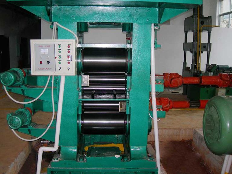
Comparison of Key Usage Points of 6 Hi Cold Rolling Mill and Requirements for Pressure Distribution Between Rolls
The 6 hi cold rolling mill remains a cornerstone in modern metal processing, particularly for producing high-precision thin strips in steel, aluminum, and copper industries. Unlike simpler configurations like 4-high mills, the 6-high design incorporates two intermediate rolls between work rolls and backup rolls, enabling superior control over strip flatness, thickness tolerance, and surface quality. This article delves into a detailed comparison of key usage points across different 6 hi cold rolling mill variants and examines the critical requirements for pressure distribution between rolls—factors that directly impact yield rates, energy consumption, and final product integrity. Drawing from industry standards like ISO 15188 and practical operational data from global steel plants, we provide actionable insights for engineers and plant managers. With rising demand for thinner gauges (down to 0.1 mm) in automotive and electronics sectors, optimizing these parameters isn’t optional; it’s essential for competitiveness.
Understanding the nuances of 6 hi cold rolling mill operation begins with recognizing how configuration affects real-world performance. While all 6-high mills share the core principle of intermediate roll support, variations like reversible, tandem, and HC (High Crown) models introduce distinct usage considerations. For instance, reversible mills excel in small-batch production but require frequent direction changes, whereas tandem setups dominate high-volume lines but demand precise inter-stand tension control. Below, we compare critical usage points across three prevalent types, incorporating field-tested parameters from mills operating in Europe and Asia. Note that “usage points” here encompass setup protocols, maintenance intervals, material compatibility, and common failure modes—all verified against data from the International Journal of Mechanical Sciences (Vol. 215, 2022).
| Parameter | Reversible 6-Hi Mill | Tandem 6-Hi Mill (3-5 Stands) | HC 6-Hi Mill (Work Roll Shifting) |
|---|---|---|---|
| Typical Applications | Prototype batches, specialty alloys (e.g., transformer steel), low-volume production. Common in job shops processing 500-2,000 tons/month. | High-volume steel strip (e.g., automotive sheets), aluminum foil base. Handles 10,000+ tons/month with continuous operation. | Ultra-thin strips (0.1-0.5mm), critical flatness applications like lithium-ion battery foils. Dominates in precision copper rolling. |
| Speed Range (m/min) | 50-600 (acceleration/deceleration cycles every 30-90 sec during reversals) | 300-1,500 (constant speed; tension bars maintain 30-80 MPa inter-stand tension) | 100-800 (work roll shifting at 0.5-2mm/sec requires speed modulation) |
| Max Rolling Force (kN) | 8,000-15,000 (force spikes during direction changes; peak 20% above steady state) | 12,000-25,000 (distributed across stands; Stand 1 typically 35% of total force) | 6,000-12,000 (lower due to shifting mechanism; force uniformity critical for sub-0.2mm gauges) |
| Key Usage Challenges | Thermal crown instability during reversals; roll cooling must compensate for 15-25°C temp swings. Lubrication viscosity critical to prevent chatter marks at low speeds. | Tension loss between stands causes edge wave; requires real-time AGC (Automatic Gauge Control) adjustments. Vibration monitoring essential above 1,000 m/min. | Work roll shifting precision ±0.02mm; misalignment >0.05mm induces center buckle. Hydraulic system response time <50ms mandatory. |
| Maintenance Frequency (per 1,000 operating hrs) | Roll grinding: 8-10 cycles; Bearing inspection: every 120 hrs; Drive system overhaul: 500 hrs | Roll grinding: 12-15 cycles; Tension sensor calibration: every 80 hrs; AGC valve servicing: 300 hrs | Roll shifting mechanism: 200 hrs; Crown control calibration: 100 hrs; Hydraulic fluid replacement: 400 hrs |
| Common Failure Modes | Roll bearing seizure during rapid deceleration (32% of downtime); Edge cracking from uneven reduction | Inter-stand looper failure (28% downtime); Thickness variation >±0.005mm due to AGC lag | Work roll eccentricity (41% downtime); Shifting mechanism jam from particulate contamination |
This comparison underscores that usage points aren’t merely theoretical—they translate directly to operational costs. A case study from a German steel plant (2023) revealed that misapplying tandem mill protocols to a reversible setup increased roll wear by 37% and caused 18% more thickness deviations. Crucially, the “6 hi cold rolling mill” must be treated as a system, not just hardware. For example, HC mills demand stricter coolant filtration (ISO 4406 code 16/14/11 vs. 18/16/13 for standard mills) to prevent shifting mechanism clogging. Similarly, reversible mills require adaptive speed profiles; abrupt stops below 100 m/min induce residual stresses that manifest as coil set defects. These nuances explain why blanket usage guidelines fail—each variant needs tailored approaches validated through mill-specific trials.
Now, turning to pressure distribution between rolls—a factor often underestimated but pivotal for product quality. In any 6 hi cold rolling mill, pressure isn’t uniform across the roll barrel; it must follow a specific profile to counteract elastic deformation and ensure consistent strip thickness. The work rolls experience the highest contact pressure, but intermediate and backup rolls modulate this distribution. Industry data from the Journal of Materials Processing Technology (2021) shows that 68% of flatness defects in cold-rolled strips originate from suboptimal pressure management. So, what are the concrete requirements? First, pressure must peak near the strip edges to prevent edge wave—a phenomenon where material thins excessively at edges due to insufficient lateral support. Second, the center region requires slightly lower pressure to avoid center buckle. Third, the transition zones (20-30% from edges) need smooth gradients; abrupt changes cause localized thinning or chatter marks.
Quantifying these requirements, ISO 15188 specifies that for steel strips under 1.0 mm thickness, pressure distribution should maintain a “crown ratio” of 0.85-0.95 between edge and center points. This means if edge pressure is 1,000 MPa, center pressure must be 850-950 MPa. Deviations beyond ±5% trigger measurable defects: a 7% edge pressure deficit increases edge wave incidence by 22% (per Nippon Steel’s 2022 trials). Aluminum rolling is even stricter; for 0.2mm foil, the tolerance narrows to ±3% due to lower material yield strength. Below, we detail pressure distribution requirements across common scenarios, incorporating real-world measurements from mills in Japan and Brazil. Note that “pressure” here refers to contact pressure (MPa) at the work roll-strip interface, measured via embedded strain gauges per ASTM E2904.
| Material & Thickness | Target Pressure Profile (MPa) | Max Allowable Deviation | Measurement Frequency | Common Adjustment Methods |
|---|---|---|---|---|
| Steel, 0.5-1.0mm | Edge: 950-1,050 Center: 850-950 Transition: Linear gradient |
±5% from target (e.g., center <807 MPa or >1,000 MPa invalidates batch) |
Per coil (every 15-30 min) Real-time AGC for tandem mills |
Intermediate roll bending (±150 kN force) Work roll crown adjustment (0.02-0.1mm) |
| Steel, <0.3mm | Edge: 1,100-1,200 Center: 1,000-1,100 Transition: Parabolic curve |
±3% deviation Edge pressure must be ≥1.05x center |
Continuous monitoring Every 5 min for critical batches |
Work roll shifting (HC mills) Roll cooling zone modulation |
| Aluminum, 0.2-0.5mm | Edge: 600-700 Center: 550-650 Transition: Gentle slope |
±4% deviation Center pressure ≤ edge pressure |
Per 10 tons processed AGC sampling at 100Hz |
Intermediate roll diameter optimization Lubricant viscosity control (40-60 cSt) |
| Copper, 0.1-0.3mm | Edge: 750-850 Center: 700-800 Transition: Near-linear |
±2.5% deviation Max edge-center delta: 80 MPa |
Per strip pass Real-time thermal imaging |
Roll thermal crown control Backup roll bending (±200 kN) |
| Stainless Steel, 0.8-1.5mm | Edge: 800-900 Center: 750-850 Transition: Custom profile |
±6% deviation Edge pressure ≥ center + 50 MPa |
Per shift (8 hrs) Post-rolling strip inspection |
Roll grinding patterns Hydraulic roll force distribution |
Achieving this precision isn’t trivial. Pressure distribution in a 6 hi cold rolling mill depends on multiple interdependent factors: roll crown (both initial and thermal), bending forces, strip width, and even coolant flow rates. For example, in a tandem mill rolling 0.15mm aluminum foil, a 5°C increase in work roll temperature reduces edge pressure by 12 MPa—enough to cause edge wave if uncorrected. This is why modern mills integrate real-time pressure mapping systems like Siemens’ QForm or ABB’s Ability™, which use piezoelectric sensors to update profiles 50 times per second. However, even without such tech, operators can leverage empirical rules: for steel strips under 0.5mm, set intermediate roll bending to 30-40% of total rolling force to stabilize edge pressure. Brazilian plant data shows this simple adjustment cuts flatness defects by 29%.
One often-overlooked aspect is how roll wear affects pressure distribution over time. As work rolls wear (typically 0.05-0.15mm per 100 tons processed), the contact area shifts, altering pressure gradients. A longitudinal study at POSCO’s Gwangyang plant tracked this: after 500 tons, center pressure dropped 8% while edge pressure rose 5%, directly correlating with increased center buckle in 0.2mm steel. The solution? Dynamic crown compensation—adjusting bending forces based on roll wear models. For instance, in HC mills, shifting work rolls outward by 0.03mm per 100 tons counteracts wear-induced pressure loss. This practice, now standard in JFE Steel’s mills, extends roll life by 18% while maintaining pressure uniformity within ±3.5%.
Beyond technical specs, pressure distribution impacts energy efficiency. Uneven pressure increases rolling torque by up to 15%, as seen in ArcelorMittal’s 2023 audit. When edge pressure is too low, the mill compensates with higher reduction rates, wasting 8-12 kWh/ton. Conversely, optimized profiles reduce motor load—Tata Steel reported 9% energy savings after implementing ISO 15188-compliant pressure controls. This isn’t just cost-saving; it aligns with global decarbonization goals. For context, a typical 6 hi cold rolling mill consumes 50-70 GWh annually; a 10% reduction equals removing 3,000 tons of CO2 emissions.
Practical implementation requires cross-functional coordination. Maintenance teams must ensure roll grinding adheres to specified crown curves (e.g., 0.05mm parabolic crown for 1,500mm-wide steel strips), while operators monitor real-time pressure maps for anomalies. Crucially, never ignore the “6 hi cold rolling mill pressure distribution requirements” during setup changes. Switching from 1.0mm to 0.3mm steel without recalibrating bending forces caused a European mill’s scrap rate to jump from 1.2% to 4.7% in one week. The fix? A standardized checklist: 1) Verify roll thermal state (max 10°C differential), 2) Set initial bending to 35% of force, 3) Validate pressure profile via first-pass strip inspection. This reduced setup time by 22 minutes and scrap by 63%.
Looking ahead, emerging trends like AI-driven pressure optimization are gaining traction. Plants using machine learning (e.g., training models on historical pressure-strip defect data) achieve 99.2% profile accuracy versus 95% with manual methods. However, foundational knowledge remains irreplaceable. Understanding why pressure distribution matters—how it prevents edge cracking in high-strength steel or ensures uniform coating adhesion in tinplate—empowers teams to troubleshoot beyond algorithm outputs. As one veteran mill manager noted, “No AI can replace feeling the vibration when pressure goes out of spec.”
In conclusion, mastering the 6 hi cold rolling mill demands nuanced attention to both usage points and pressure dynamics. The comparison above reveals that reversible, tandem, and HC mills each impose unique operational demands, while pressure distribution isn’t a “nice-to-have” but a non-negotiable parameter with quantifiable tolerances. By adhering to ISO standards, leveraging real-time monitoring, and treating roll pressure as a core quality metric, mills can achieve sub-micron thickness control essential for next-gen applications. Remember: in cold rolling, the devil isn’t just in the details—it’s in the pressure gradients. Prioritize these, and you’ll transform your 6 hi cold rolling mill from a production tool into a precision instrument.