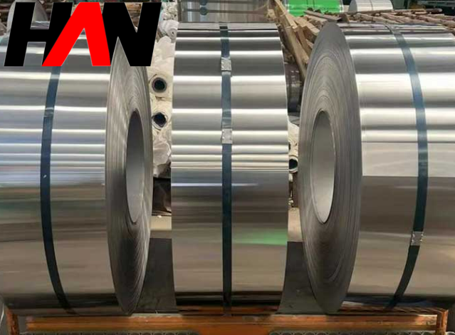
Daily Operation Matters of 6 Hi Cold Rolling Mill
An In-Depth Guide to the 6-Hi Cold Rolling Mill Process
The cold rolling industry stands as a cornerstone of modern manufacturing, producing high-precision, superior-quality steel and non-ferrous metal strips for a vast array of applications, from automotive bodies to home appliances and precision electronics. At the heart of this advanced manufacturing landscape is the 6-Hi Cold Rolling Mill. Unlike its 4-Hi predecessor, the 6-Hi configuration offers unparalleled control over strip shape and thickness, enabling the production of thinner, harder, and flatter materials. Mastering the daily operation of this sophisticated machinery is not merely a task; it is a science that blends mechanical understanding, metallurgical knowledge, and procedural discipline. This comprehensive guide delves into the critical daily operation matters of the 6-Hi cold rolling mill process, providing actionable insights, technical parameters, and troubleshooting strategies for operators and engineers striving for excellence.
1. The Anatomy of a 6-Hi Mill: Understanding the Roll Stack
The “6-Hi” designation refers to the six-roll configuration in the mill stand, a design engineered for maximum stability and shape control. Each roll plays a distinct and vital role:
- Work Rolls (WR): The two smallest-diameter rolls that are in direct contact with the metal strip. Their small diameter reduces the rolling force required for a given reduction, which is crucial for rolling hard and thin materials.
- Intermediate Rolls (IMR): Positioned between the work rolls and backup rolls, these two rolls provide primary support to the work rolls, preventing them from bending horizontally. Crucially, they are the main actuators for shape control through axial shifting.
- Backup Rolls (BUR): The largest and heaviest rolls in the stack. They provide the immense vertical support needed to counteract the massive rolling forces, preventing vertical deflection of the work and intermediate rolls and ensuring consistent strip thickness.
This hierarchical structure allows for the precise distribution of rolling forces, minimizing roll deflection and enabling the sophisticated shape control mechanisms that define the 6-Hi cold rolling mill process. Understanding this mechanical synergy is the first step toward effective operation.
2. Pre-Operational Checklist: The Foundation of a Smooth Shift
A successful rolling campaign begins long before the strip is threaded. A rigorous pre-operational check is non-negotiable to ensure equipment readiness, operator safety, and product quality. Daily checks should be systematic and documented.
Daily Pre-Start Inspection Protocol
| System/Component | Check Point | Standard/Parameter | Action if Deviated |
|---|---|---|---|
| Hydraulic System | Main pressure, fluid level, filter indicators | Pressure: 180-210 bar (typical); Level: >75%; No filter alarms | Do not start. Investigate cause (leak, pump issue), top up fluid, replace filter. |
| Lubrication System | Backup roll bearing oil level, grease points | Oil level within sight glass; Grease system pressure normal | Refill oil/grease. Check for leaks or blockages in lines. |
| Rolling Emulsion (Coolant) | Concentration, temperature, pH, filter pressure | Concentration: 3-8% (material dependent); Temp: 45-55°C; pH: 8.5-9.5 | Adjust concentration, check heaters/coolers, dose pH adjuster, backflush filters. |
| Roll Stack | Roll surfaces, chock alignment, coolant spray nozzles | No visible spalling, cracks, or marks. Nozzles clear and correctly aimed. | Report roll defects for immediate change. Clean or replace blocked nozzles. |
| Safety Systems | Emergency stops, light curtains, interlocks | Test functionality of all E-stops and safety guards. | Lock-out/Tag-out the machine and contact maintenance immediately. |
3. Core Process Control: Mastering the Parameters
The essence of the 6-Hi cold rolling mill process lies in the precise, real-time manipulation of several key parameters. These elements are interconnected; a change in one will invariably affect the others.
3.1 Pass Schedule Design
A pass schedule is the roadmap for thickness reduction. It dictates the percentage of reduction for each pass the strip makes through the mill. A well-designed schedule balances productivity with quality, avoiding material overload and ensuring the final product meets mechanical property specifications. Factors include material grade (yield strength, work hardening rate), initial and final thickness, and mill power limitations.
Example Pass Schedule: Low Carbon Steel (SPCC)
Objective: Reduce from 2.5 mm to 0.5 mm
| Pass No. | Entry Thickness (mm) | Exit Thickness (mm) | Reduction (%) | Rolling Speed (m/min) |
|---|---|---|---|---|
| 1 | 2.50 | 1.60 | 36.0% | 450 |
| 2 | 1.60 | 1.00 | 37.5% | 600 |
| 3 | 1.00 | 0.70 | 30.0% | 800 |
| 4 | 0.70 | 0.55 | 21.4% | 1000 |
| 5 (Skin Pass) | 0.55 | 0.50 | 9.1% | 1100 |
3.2 Tension Control: The Art of Pulling
Tension, applied by the uncoiler (back tension) and recoiler (front tension), is critical for stability and flatness. The tension is set as a specific stress, calculated as a percentage of the material’s current yield strength. As the material is cold-worked, its yield strength increases, requiring the tension settings to be adjusted for each pass.
- General Rule: The unit tension (stress) is typically set between 10% and 40% of the material’s yield strength (σs).
- Safety Margin: It is highly advisable not to exceed 50% of the yield strength, as this significantly increases the risk of strip necking or breakage, especially if there are any edge defects on the strip.
- Function: Back tension helps ensure the strip enters the roll bite flat and stable. Front tension is a primary tool for controlling strip flatness on the exit side. Higher front tension can help pull out minor shape defects like center buckle.
3.3 Shape Control: The 6-Hi Mill’s Superpower
This is where the 6-Hi mill truly excels. “Shape” or “flatness” refers to the absence of internal stress variations that cause defects like wavy edges or center buckles. The operator has a powerful toolkit to control shape:
-
Intermediate Roll (IMR) Axial Shifting: This is the most potent shape control method. By shifting the IMRs horizontally, the operator changes the distribution of support force onto the work roll.
- Shifting IMRs outward (away from the center) effectively creates a “concave” work roll profile, directing more rolling force to the center of the strip. This is used to correct wavy edges.
- Shifting IMRs inward (toward the center) creates a “convex” work roll profile, directing more force to the edges. This is used to correct center buckle.
-
Roll Bending (Work Roll & IMR): Hydraulic cylinders apply force to the ends of the work roll and/or intermediate roll chocks.
- Positive Bending pushes the roll ends apart, creating a more convex or “crowned” roll barrel. This helps correct center buckle.
- Negative Bending pulls the roll ends together, creating a more concave profile. This helps correct wavy edges.
- Zonal Cooling: A series of spray headers are arranged across the width of the work rolls. By selectively increasing or decreasing coolant flow to specific zones, the operator can locally shrink or expand the roll diameter via thermal effects. This provides very fine, localized shape control, ideal for correcting quarter buckles or other complex shape issues.
3.4 Automatic Gauge Control (AGC)
The AGC system is the brain of thickness control. It uses high-precision thickness gauges (typically X-ray or isotope-based) at the mill exit to measure the strip thickness in real-time. If a deviation from the setpoint is detected, the AGC system instantly adjusts the roll gap, primarily through the mill’s high-response hydraulic screw-down cylinders. This closed-loop feedback system ensures thickness tolerances as tight as ±0.001 mm can be maintained even at high rolling speeds.
4. Roll Management: The Consumable Heart of the Mill
As noted in many operational guides, rolls are not permanent fixtures; they are high-value consumables with a defined lifecycle. Proper management is crucial for both quality and cost control.
- Work Roll Lifecycle: A work roll’s life in the mill is measured by a “campaign,” typically defined by the total tonnage rolled (e.g., 800-1200 tons) or a set number of hours. After a campaign, the roll surface will have worn down and may exhibit micro-cracks or other fatigue damage.
- Roll Grinding: After being removed from the mill, work rolls are sent to the roll shop for grinding. A precise layer of the surface is removed to restore the desired surface roughness (Ra), profile (crown), and eliminate any surface defects. The roll diameter is reduced with each grind.
- Inventory and Tracking: A robust system must be in place to track each roll’s history: current diameter, total tonnage rolled, number of grinds, and any observed defects. This data is vital for predicting roll life, scheduling changes, and troubleshooting quality issues that may be roll-related. Intermediate and backup rolls have much longer campaign lives but follow the same principle of periodic inspection and grinding.
5. Troubleshooting Common Rolling Defects
Even with perfect preparation, issues can arise. A skilled operator can quickly diagnose a problem and apply the correct solution, minimizing scrap and downtime. Here is a guide to common defects in the 6-Hi cold rolling mill process.
| Defect | Probable Cause(s) | Corrective Action(s) |
|---|---|---|
| Wavy Edges (Strip is longer at the edges than the center) |
– Excessive reduction at edges. – Roll thermal crown too small. – Insufficient positive roll bending. |
– Shift IMRs outward. – Decrease coolant flow at strip edges. – Increase positive bending or decrease negative bending. |
| Center Buckle (Strip is longer at the center than the edges) |
– Excessive reduction at the center. – Roll thermal crown too large. – Excessive positive roll bending. |
– Shift IMRs inward. – Increase coolant flow at strip center. – Decrease positive bending or apply negative bending. – Increase front tension. |
| Strip Breakage | – Excessive tension. – Poor quality incoming coil (edge cracks). – Over-reduction in one pass. – Poor lubrication. |
– Reduce front/back tension settings. – Inspect incoming coil and trim edges if necessary. – Revise pass schedule. – Check coolant concentration and flow. |
| Surface Scratches | – Debris in the roll bite (metal fines). – Damaged guide rollers or seals. – Contaminated rolling emulsion. |
– Increase coolant flushing. – Inspect and clean/replace all strip contact points. – Check coolant filtration system. |
| Chatter Marks (Periodic transverse marks) |
– Mill vibration (third-octave chatter). – Worn roll bearings. – Improper roll grinding. |
– Adjust rolling speed (often reducing it slightly can shift the harmonic). – Schedule maintenance to inspect bearings. – Change the work rolls. |
Conclusion: A Commitment to Precision
The daily operation of a 6-Hi cold rolling mill is a dynamic and demanding discipline. It requires more than just following a procedure; it demands a deep understanding of the intricate interplay between machine, material, and process parameters. From the diligence of pre-operational checks to the finesse of real-time shape control and the foresight of proactive maintenance, every action contributes to the final product’s quality and the operation’s efficiency. By mastering the principles of pass schedules, tension control, and the powerful shape correction tools available, operators can fully leverage the capabilities of the 6-Hi mill. This commitment to precision ensures the consistent production of high-quality flat-rolled products that meet the ever-increasing demands of modern industry, solidifying the critical role of the 6-Hi cold rolling mill process in the world of advanced manufacturing.