Comparison of Selection Precautions for Different Specifications of 6 Hi Cold Rolling Mill and Movement Requirements of Intermediate Rolls
In the realm of modern metallurgy and strip processing, the 6 hi cold rolling mill stands as a pinnacle of precision engineering. Unlike conventional rolling equipment, the six-high configuration offers superior flatness control and thickness reduction capabilities, making it indispensable for processing high-precision steel, stainless steel, copper, and aluminum strips. This comprehensive guide delves into the nuanced comparison of selection precautions for different specifications of these mills and explores the critical movement requirements of intermediate rolls—a feature that defines the 6-hi technology.
1. Engineering Principles of the 6 Hi Cold Rolling Mill
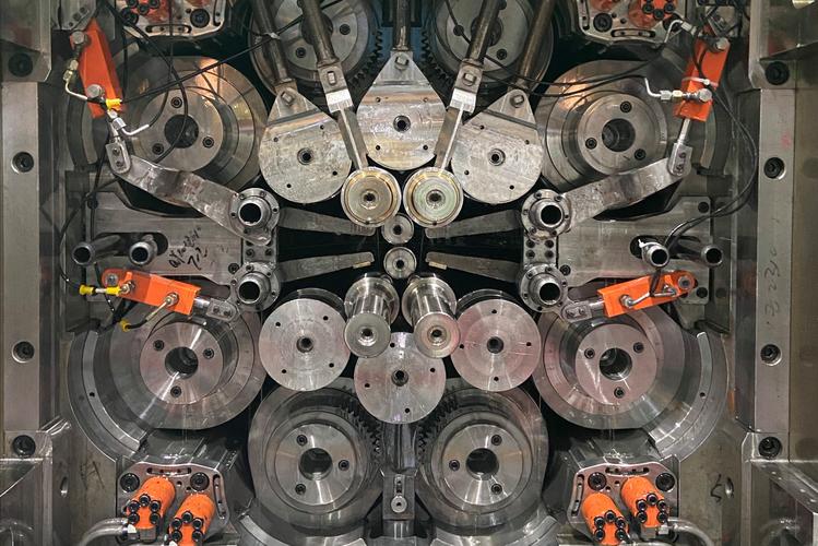
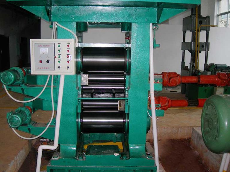
To understand the selection criteria, one must first grasp the mechanical advantage of the 6 hi cold rolling mill. While a 4-hi mill consists of two work rolls and two backup rolls, the 6-hi configuration introduces a pair of Intermediate Rolls (IMR) between the work rolls and backup rolls. This architecture is not merely about adding components; it is about altering the physics of deformation.
The primary function of the intermediate roll is to decouple the deflection of the backup roll from the work roll. By utilizing axial shifting technology, the 6-hi mill can effectively eliminate the “harmful contact area” between rolls, allowing for better control of the strip edge drop and overall flatness (shape). This makes the 6-hi mill the preferred choice for rolling thinner gauges (below 0.2mm) and harder materials where roll deflection would otherwise compromise quality.
2. Comparison of Selection Precautions for Different Specifications
Selecting a 6 hi cold rolling mill is not a “one-size-fits-all” process. The precautions vary significantly based on the mill’s size specification, intended material application, and target output. We can categorize these specifications into Light/Precision Duty (narrow width) and Heavy Duty (wide width).
2.1 Precautions for Small Specification Mills (Width < 650mm)
Small specification mills are typically used for precision electronics materials, copper alloys, or narrow stainless steel strips.
- Rigidity vs. Precision: For small mills, the focus is less on massive rolling force and more on precision. Buyers must caution against selecting oversized hydraulic cylinders which can reduce control sensitivity. The servo valve response time for AGC (Automatic Gauge Control) is critical here.
- Thermal Stability: Small rolls heat up faster. A key precaution is ensuring the cooling system design is adequate for the specific surface area of the work rolls. Unlike large mills, small mills have less thermal mass to dissipate heat.
- Tension Control: For thin, narrow strips, tension fluctuations can cause breakage. Selection must prioritize high-precision tension reels with low-inertia motors.
2.2 Precautions for Large Specification Mills (Width > 1250mm)
Large mills process wide coils for automotive or appliance panels. The dynamic forces here are exponential.
- Housing Stiffness: The most critical selection precaution is the Mill Modulus. For wide mills, housing stretch under load can be significant. Buyers must verify the finite element analysis (FEA) of the mill stand to ensure minimal deformation under maximum rolling force (e.g., 18000 kN).
- Backup Roll Bearings: In large specs, the oil film bearings or four-row cylindrical roller bearings must be selected based on load capacity and speed. Incorrect bearing selection leads to catastrophic failure under heavy reduction passes.
- Crown Control Capacity: Wide strips are prone to complex flatness defects (quarter buckle). The selection must ensure the bending force range (both positive and negative) is sufficient to counteract the width-to-thickness ratio.
Table 1: Technical Parameter Comparison for Selection Reference
| Parameter / Spec | AGM-450 (Precision) | AGM-850 (Medium) | AGM-1450 (Heavy) |
|---|---|---|---|
| Max Strip Width | 450 mm | 850 mm | 1450 mm |
| Max Rolling Force | 4000 kN | 10000 kN | 18000 kN |
| Rolling Speed | Max 600 m/min | Max 1000 m/min | Max 1400 m/min |
| Intermediate Roll Shifting | +/- 75 mm | +/- 150 mm | +/- 250 mm |
| Primary Application | Electronic parts, Springs | Hardware, Cutlery | Automotive body, Appliances |
3. Movement Requirements of Intermediate Rolls (IMR)
The defining feature of the 6 hi cold rolling mill is the movement capability of the intermediate rolls. This is not a passive feature but an active control mechanism. The movement requirements are stringent and scientifically derived to ensure the stability of the rolling process. Correct execution of IMR movement is a mandatory operational requirement.
3.1 Axial Shifting Mechanism Requirements
The intermediate rolls must shift axially (sideways) relative to the strip. The core requirement here is positional accuracy. In modern HC (High Crown) mills, the shifting system is typically driven by hydraulic cylinders or servo-electric screws.
Why is this required? The shifting aligns the barrel end of the intermediate roll with the edge of the strip. This eliminates the “overhanging” contact pressure that causes edge waves in 4-hi mills. The movement requirement dictates that the shift position must be recalculated and adjusted for every coil width change. A failure to synchronize the shift with the strip width will result in either disastrous edge drops (if under-shifted) or roll spalling marks on the strip surface (if over-shifted).
3.2 Bending Force Dynamics
Movement is not just axial; it is also vertical via bending blocks. The intermediate rolls are subjected to powerful hydraulic bending forces (Positive and Negative Bending).
- Requirement 1: Hysteresis Control. The movement of the bending cylinders must have minimal hysteresis. When the Automatic Flatness Control (AFC) commands a change in pressure, the IMR chocks must move instantly. Any mechanical friction in the sliding blocks (typically lined with manganese bronze or polymer plates) must be minimized.
- Requirement 2: Load Balancing. The movement must be symmetrical. If the drive side (DS) and operator side (OS) cylinders do not move in perfect unison, the roll gap becomes wedge-shaped, causing the strip to camber (steer) and potentially crash into the housing.
3.3 Synchronization with Rolling Speed
A critical but often overlooked movement requirement is the dynamic shifting during operation (Dynamic Shape Roll – DSR). Advanced 6 hi cold rolling mills allow for IMR shifting under load. The requirement here is that the shifting speed must be controlled to prevent spiraling marks on the backup rolls. The hydraulic system must be capable of overcoming the tremendous friction caused by the rolling force (which can exceed 1000 tons) to move the roll axially.
4. Maintenance and Accuracy Considerations
To maintain the movement accuracy of the intermediate rolls, strict maintenance protocols are required. This ensures the longevity of the mill and the quality of the product.
Key Maintenance Points for IMR Systems:
1. Axial Locking Mechanism: The device that connects the shifting cylinder to the roll chock must be inspected weekly. Wear in this linkage creates “backlash,” leading to inaccurate positioning of the roll barrel edge.
2. Lubrication of Shifting Plates: The sliding surfaces that allow the intermediate roll to shift withstand immense vertical loads. Specialized high-viscosity lubricants or oil-mist lubrication systems are required to prevent stick-slip phenomena.
3. Roll Grinding Profiles: The IMR usually has a specific taper or CVC (Continuously Variable Crown) profile. When grinding these rolls, the geometric tolerance must be within +/- 0.005mm. If the profile is incorrect, the shifting movement will not produce the desired flatness correction.
5. Real-world Production Case Study
Consider a manufacturing plant producing high-grade electrical steel (silicon steel) using a 1250mm 6-Hi Reversing Cold Mill. The material is extremely hard and brittle.
Challenge: The incoming hot-rolled band has a slight edge wave. In a standard 4-hi mill, operators would struggle to remove this without breaking the strip edges.
6-Hi Solution Application: The operators utilize the 6-hi capabilities. They set the Intermediate Roll Shift to match the strip width minus 30mm. This effectively creates a “soft edge” in the roll gap pressure distribution. Simultaneously, positive intermediate roll bending is applied at 350kN.
Result: The shifting movement effectively isolates the work roll bending from the backup roll contact. The edge wave is eliminated, and the strip is reduced from 2.5mm to 0.35mm with a flatness tolerance of less than 5 I-Units. This demonstrates that correct selection (high rigidity mill) combined with precise IMR movement is the key to profitability in cold rolling.
6. Conclusion
The selection of a 6 hi cold rolling mill requires a multidimensional analysis comparing mill rigidity, thermal characteristics, and automation levels across different specifications. Whether choosing a compact 450mm unit for copper foil or a massive 1450mm unit for automotive steel, the underlying physics remain the same, but the engineering priorities shift.
Furthermore, the movement requirements of the intermediate rolls—encompassing axial shifting precision, hydraulic response speed, and mechanical synchronization—are the heart of the 6-hi technology. Operational success depends on the rigorous application of these movement protocols. By adhering to these scientific selection criteria and operational standards, manufacturers can maximize the efficiency and product quality of their cold rolling lines.