Technical Principles and Daily Maintenance Items of Cold Rolling Mills
A Deep Dive into the Cold Rolling Mill Process
The cold rolling mill process is a cornerstone of modern metalworking, responsible for producing high-quality, dimensionally precise, and surface-finished metal strips and sheets. Unlike hot rolling, which occurs above the metal’s recrystallization temperature, cold rolling is a metal forming process performed at or near room temperature. This fundamental difference imparts unique mechanical properties and superior surface characteristics to the final product, making it indispensable for industries ranging from automotive and aerospace to consumer electronics and construction. This comprehensive guide will explore the intricate technical principles governing the cold rolling mill process, detail the various types of mills, and provide an exhaustive checklist for daily, weekly, and long-term maintenance to ensure optimal performance, longevity, and product quality.
Section 1: The Step-by-Step Cold Rolling Mill Process Flow
The transformation of a hot-rolled coil into a precision cold-rolled product is a multi-stage journey. Each step is meticulously controlled to achieve the desired final specifications. Understanding this workflow is crucial for anyone involved in the production or use of cold-rolled materials.
- Coil Preparation (Pickling & Annealing): The process begins with a hot-rolled coil. This coil first undergoes pickling, an acid bath treatment (typically using hydrochloric or sulfuric acid) to remove the iron oxide scale (mill scale) from its surface. Any residual scale would be pressed into the strip during rolling, causing severe surface defects. For some materials, an initial annealing step may be required to soften the metal and improve its ductility for the subsequent reduction process.
- Uncoiling and Feeding: The prepared coil is mounted on an uncoiler (or pay-off reel). The leading edge of the strip is fed through leveling rollers to remove any coil set (the natural curvature of the strip) and then guided into the first stand of the cold rolling mill.
- The Rolling (Reduction) Stage: This is the heart of the cold rolling mill process. The strip passes through a pair of powerful, rotating work rolls. The gap between these rolls is smaller than the incoming strip’s thickness, forcing the metal to deform plastically. This reduces its thickness and increases its length. The process is often performed in multiple passes or through a series of mill stands (in a tandem mill) to achieve the final target gauge.
- Tension Control: Precise tension must be maintained on the strip both before it enters the rolls (back tension) and after it exits (front tension). This is controlled by the uncoiler and the recoiler (or tension reel). Proper tension is critical for tracking the strip correctly through the mill, preventing slippage, and, most importantly, controlling the flatness of the finished product.
- Lubrication and Cooling: A specialized rolling fluid (an oil-in-water emulsion or neat oil) is continuously sprayed onto the rolls and the strip. This fluid serves two vital purposes:
- Lubrication: It reduces friction between the rolls and the strip, which lowers the required rolling force and energy consumption, and prevents metal from sticking to the rolls.
- Cooling: The immense pressure and deformation generate significant heat. The fluid dissipates this heat, keeping the strip and rolls below the recrystallization temperature and controlling the thermal profile (thermal crown) of the rolls.
- Gauging and Automatic Control: Modern mills are equipped with sophisticated measurement and control systems. Non-contact thickness gauges (often using X-rays or isotopes) continuously measure the strip’s thickness as it exits the roll gap. This data is fed to an Automatic Gauge Control (AGC) system, which instantly adjusts the roll gap or strip tension to correct any deviations from the target thickness.
- Recoiling: After passing through the final mill stand and being verified for gauge and surface quality, the finished strip is wound tightly onto a recoiler (or tension reel), forming a new, finished coil. The coil is then strapped and removed for further processing (like annealing, temper rolling, or slitting) or shipment.
Section 2: Core Technical Principles and Mill Configurations
The effectiveness of a cold rolling mill hinges on the precise application of metallurgical and mechanical principles. The configuration of the rolls is a primary determinant of the mill’s capability and the quality of the product it can produce.
Roll Configurations: From Simple to Advanced
The arrangement of rolls within a mill stand defines its type and application. The core components are the Work Rolls, which are in direct contact with the strip, and the Backup Rolls, which support the work rolls and prevent them from bending under the immense rolling forces.
| Mill Type | Roll Configuration | Primary Application | Key Advantages & Characteristics |
|---|---|---|---|
| Two-High Mill | Two large-diameter work rolls. | Skin-pass or temper rolling, breaking down scale on hot-rolled products. | Simple design. Limited reduction capability due to high roll deflection (bending). |
| Four-High Mill | Two small-diameter work rolls supported by two large-diameter backup rolls. | The most common configuration for cold rolling of steel and aluminum sheet and strip. | Small work rolls reduce rolling force and power consumption. Backup rolls provide rigidity and prevent work roll bending, enabling higher reductions and better gauge control. |
| Six-High (HC/UCM) Mill | Two work rolls, two intermediate rolls, and two backup rolls. | High-quality strip with excellent flatness control, especially for thin or hard materials. | Intermediate rolls can be shifted axially and bent, providing powerful control over the strip’s cross-sectional profile (flatness). Offers superior shape control compared to a 4-High mill. |
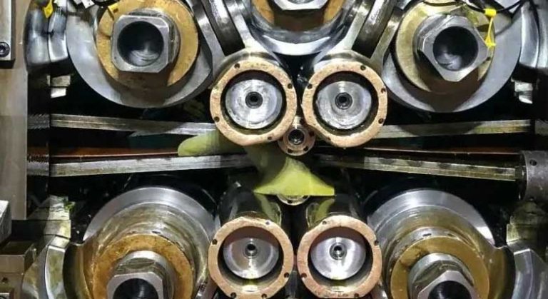
| Twenty-High (Sendzimir) Mill | A cluster of 20 rolls: two very small work rolls supported by a cascade of backing bearings and rolls in a rigid housing. | Precision rolling of very thin, hard, and high-strength materials like stainless steel, silicon steel, and special alloys. | Extremely rigid housing and tiny work rolls allow for massive reductions per pass and the production of ultra-thin foil with exceptional gauge tolerance. |
Key Process Parameters and Their Influence
Mastering the cold rolling mill process requires a delicate balance of several critical parameters. These are continuously monitored and adjusted by advanced control systems to ensure consistent product quality.
Critical Process Parameters Overview
The interplay between Reduction, Speed, Tension, and Lubrication defines the outcome of the rolling process. An imbalance in any one of these can lead to defects in gauge, flatness, or surface finish. Modern mills use sophisticated models to predict and control these interactions in real-time.
| Parameter | Description | Impact on Process & Product | Typical Values (Low Carbon Steel Example) |
|---|---|---|---|
| Reduction per Pass (%) | The percentage decrease in thickness achieved in a single pass through the rolls. | Higher reduction increases productivity but requires more force, generates more heat, and increases work hardening. | 20% – 50% |
| Rolling Speed (m/min) | The speed at which the strip travels through the mill. | Affects productivity, heat generation, and lubricant film formation. Higher speeds can lead to hydrodynamic lubrication but also thermal stability challenges. | 600 – 2,200 m/min |
| Strip Tension (MPa) | The tensile stress applied to the strip at the entry (back tension) and exit (front tension). | Crucial for strip stability, tracking, and flatness control. Higher tension can reduce roll force but excessive tension can cause strip breakage. | 50 – 150 MPa |
| Roll Force (kN/m) | The total force exerted by the rolls onto the strip to cause deformation. | Determines the power consumption and stress on mill components. It is a result of material properties, reduction, and friction. | 5,000 – 15,000 kN/m |
| Lubricant/Coolant | Type, concentration, temperature, and flow rate of the rolling fluid. | Controls friction, heat removal, and surface finish. Incorrect parameters can lead to surface defects, poor shape, and thermal instability. | Emulsion: 2-8% concentration, 45-55°C |
Note: The values provided are illustrative and can vary significantly based on the specific alloy, mill type, and desired product characteristics.
Section 3: Comprehensive Maintenance for Cold Rolling Mills
The extreme forces, high speeds, and precision requirements of a cold rolling mill make a rigorous and proactive maintenance program non-negotiable. Neglecting maintenance leads to unplanned downtime, poor product quality, and potentially catastrophic equipment failure. A structured maintenance schedule, divided into daily, weekly, and periodic tasks, is the key to reliability.
Maintenance Schedule and Checklist
The following table outlines a foundational maintenance plan. This should be adapted to the specific recommendations of the mill manufacturer and the operational intensity of the facility.
| Frequency | System / Component | Maintenance Task Checklist |
|---|---|---|
| Daily (Pre/Post-Shift) | Mechanical | – Visually inspect work rolls and backup rolls for surface damage (marks, spalling, cracks). – Check for any unusual vibrations or noises during operation. – Verify all safety guards and interlocks are in place and functional. – Check for leaks in hydraulic, pneumatic, and lubrication lines. |
| Lubrication System | – Check oil levels in all hydraulic power units and gearbox reservoirs. – Verify grease levels in automatic lubrication systems. – Ensure all lubrication points are receiving lubricant. |
|
| Coolant System | – Check coolant/emulsion level in the main tank. – Verify coolant concentration using a refractometer. – Inspect main filters for high-pressure differential; clean or replace as needed. – Check that all spray nozzles are clear and providing a full spray pattern. |
|
| Electrical & Control | – Check HMI for any active alarms or warnings. – Ensure all emergency stop buttons are clear and accessible. – Visually inspect main electrical cabinets for signs of overheating or dust accumulation. |
|
| General Area | – Clean up any oil or coolant spills around the mill stand. – Ensure the operator’s control pulpit is clean and orderly. |
|
| Weekly | Mechanical | – Inspect drive spindles, couplings, and universal joints for wear and proper lubrication. – Check the tension and condition of any belt or chain drives. – Check and tighten any critical fasteners on the mill housing and chocks. |
| Hydraulic/Pneumatic | – Inspect hydraulic accumulators for correct pre-charge pressure. – Check and clean hydraulic servo-valve filters. – Drain water from pneumatic system air reservoirs and filter bowls. |
|
| Instrumentation | – Clean the windows of X-ray/isotope thickness gauges. – Perform a basic calibration check on thickness and tension measurement systems against a known standard. – Inspect sensor cabling for damage or wear. |
|
| Coolant System | – Skim tramp oil from the surface of the coolant reservoir. – Take a sample of the coolant for laboratory analysis (bacterial count, particle contamination). |
|
| Monthly / Periodic | Rolls & Bearings | – Perform scheduled roll changes. Send used rolls for grinding. – Inspect roll chock bearings during roll changes for signs of wear or damage. – Analyze vibration data from main drive motors and gearboxes to predict bearing failure. |
| Electrical & Drives | – Clean or replace air filters on drive and control cabinet cooling fans. – Perform a thorough cleaning of electrical cabinets (with power locked out). – Check electrical connections for tightness in high-power circuits. |
|
| System Calibration | – Perform a full calibration of the Automatic Gauge Control (AGC) and Automatic Flatness Control (AFC) systems. – Test and verify the accuracy of all critical process sensors. |
Section 4: Troubleshooting Common Cold Rolling Defects
Even with excellent maintenance, process issues can arise. Quickly identifying the cause of a defect is essential to minimize scrap and maintain production efficiency. The following table links common defects to their likely causes and corrective actions.
| Defect | Description | Potential Causes | Corrective Actions |
|---|---|---|---|
| Gauge Variation | Strip thickness deviates from the setpoint, either cyclically or randomly. | – Incoming material gauge variation. – Roll eccentricity (out-of-round rolls). – Worn roll neck bearings. – Poor AGC tuning. – Temperature fluctuations. |
– Improve hot-rolled coil quality. – Grind rolls to correct eccentricity. – Replace worn bearings. – Re-tune AGC gain and response settings. – Improve thermal stability of rolls and coolant. |
| Poor Flatness (Shape) | Strip is not perfectly flat. Can manifest as center buckle (long center) or edge waves (long edges). | – Uneven thickness profile of incoming strip. – Incorrect roll crown (thermal or ground). – Uneven cooling across the strip width. – Incorrect work roll bending or shifting settings. |
– Adjust AFC system (roll bending, shifting, zone cooling). – Optimize the ground crown of the work rolls for the product mix. – Clean and adjust coolant spray nozzles for uniform cooling. |
| Surface Scratches | Linear marks or scratches on the strip surface, parallel to the rolling direction. | – Debris or metal particles embedded in the rolls. – Scratches on entry/exit guides or bridles. – Contaminated rolling lubricant. |
– Polish or change the work rolls. – Inspect and polish all strip contact surfaces. – Improve coolant filtration; check for sources of contamination. |
| Chatter Marks | Transverse, periodic marks across the strip width. | – Third-octave chatter: self-excited vibration in the roll bite. – Torsional vibration from the drive system. – Worn components in the mill stand. |
– Adjust process parameters (speed, tension, reduction). – Use specially formulated anti-chatter rolling oils. – Perform vibration analysis to identify and fix the source in the drive train or mill housing. |
Conclusion: A Synthesis of Precision and Diligence
The cold rolling mill process is a sophisticated synergy of powerful mechanics, intricate control theory, and materials science. Achieving the highest standards of quality and efficiency is not merely about having advanced machinery; it is about a deep understanding of the technical principles at play and an unwavering commitment to a proactive, detailed maintenance culture. From the initial pickling of the coil to the final turn on the recoiler, every stage demands precision. By adhering to rigorous operational protocols and a structured maintenance plan, manufacturers can unlock the full potential of their cold rolling mills, ensuring the consistent production of high-value materials that form the backbone of countless modern industries.