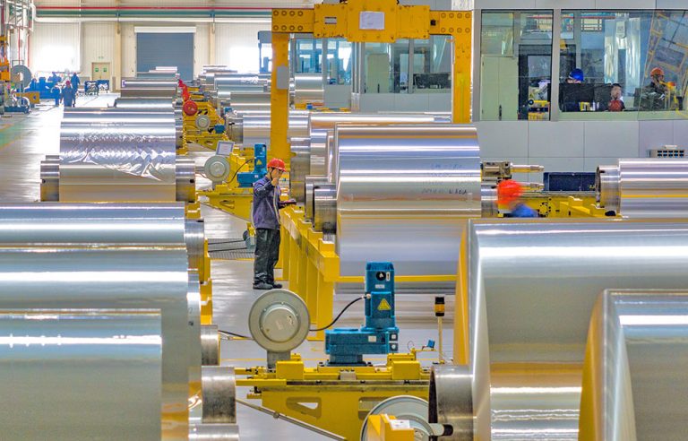
Introduction to Installation Requirements of 6 Hi Cold Rolling Mill
The installation of a 6 Hi cold rolling mill is a highly technical and precision-driven process that directly impacts the performance, product quality, and operational safety of the entire cold rolling line. Unlike simpler rolling configurations, the six-high (6 Hi) design—typically comprising two work rolls, two intermediate rolls, and two backup rolls—offers superior flatness control, reduced roll deflection, and enhanced capability for processing thin, high-strength materials such as advanced high-strength steels (AHSS), stainless steel, and specialty alloys. However, these advantages come with stringent installation requirements that must be meticulously followed to ensure optimal functionality.
Why Installation Precision Matters for a 6 Hi Cold Rolling Mill
In a 6 Hi cold rolling mill, the mechanical interaction between the six rolls creates a complex load distribution system. Even minor misalignments—on the order of micrometers—can lead to uneven roll wear, poor strip flatness, edge wave or center buckle defects, and premature bearing failure. Moreover, modern 6 Hi mills often integrate advanced control systems like Automatic Gauge Control (AGC), hydraulic roll bending, and dynamic crown control, all of which rely on precise mechanical alignment to function correctly.
Therefore, installation is not merely about placing equipment on a foundation—it involves coordinated efforts in civil engineering, mechanical alignment, hydraulic integration, electrical commissioning, and software calibration. Below, we break down the critical installation requirements into actionable categories, supported by real-world parameters and industry standards.
1. Foundation and Civil Works Requirements
The foundation is the bedrock of mill stability. For a typical industrial 6 Hi cold rolling mill with a rolling force capacity of 15–25 MN, the foundation must meet the following criteria:
| Parameter | Requirement | Standard Reference |
|---|---|---|
| Foundation Depth | ≥ 2.5 meters below finished floor level | ISO 10814-1 |
| Concrete Grade | C35/45 or higher (compressive strength ≥ 35 MPa) | EN 206 |
| Flatness Tolerance | ±0.5 mm over any 1-meter span | AGMA 6012-B06 |
| Levelness Tolerance | ≤ 0.1 mm/m along mill axis | SMS Group Guidelines |
| Vibration Isolation | Elastomeric pads or spring isolators (natural frequency ≤ 8 Hz) | ISO 10816-3 |
It is critical that the foundation curing period lasts at least 28 days before any heavy machinery is placed. Post-curing, laser leveling and optical alignment tools should verify surface conformity. Any deviations beyond tolerance must be corrected via precision grinding or epoxy grouting.
2. Mechanical Alignment and Roll Assembly
The heart of the 6 Hi mill lies in its roll stack. Proper alignment ensures uniform contact pressure and minimizes parasitic loads. Key steps include:
- Roll Centerline Alignment: All six rolls must share a common horizontal and vertical centerline within ±0.05 mm. This is verified using optical alignment systems or laser trackers.
- Roll Parallelism: Work rolls must be parallel to intermediate and backup rolls within 0.02 mm/m of roll length. Misalignment causes edge thinning or center thickening.
- Bearing Housing Fit: Clearance between roll necks and chocks should be 0.03–0.06 mm (depending on roll diameter). Excessive clearance induces chatter; too tight causes overheating.
- Hydraulic Cylinder Positioning: AGC cylinders must be coaxial with the backup roll center within ±0.1 mm to prevent side loading.
For example, in a typical 6 Hi mill designed for 1250 mm wide strip with 500 mm work roll diameter, the intermediate rolls are usually 650–750 mm in diameter, and backup rolls range from 1200–1500 mm. The roll gap setting accuracy must be better than ±2 µm for gauge control in thin-gauge applications (<0.5 mm).
3. Hydraulic and Lubrication System Integration
Modern 6 Hi mills rely heavily on hydraulic systems for roll bending, roll shifting (in HC or CVC variants), and AGC. Installation must ensure:
| System Component | Operating Pressure | Filtration Requirement | Response Time |
|---|---|---|---|
| AGC Hydraulic System | 210–315 bar | ISO 4406 Class 16/14/11 | ≤ 10 ms |
| Work Roll Bending | 140–210 bar | ISO 4406 Class 17/15/12 | ≤ 50 ms |
| Roll Cooling & Lubrication | 3–8 bar (emulsion) | 5–10 µm filtration | N/A |
All hydraulic lines must be flushed to NAS 1638 Class 6 or better before commissioning. Quick-disconnect couplings for roll change systems should be tested for zero-leak performance under full pressure. Additionally, centralized lubrication systems for roll neck bearings require timed grease injection cycles calibrated to rolling speed and load.
4. Electrical, Automation, and Control Systems
A 6 Hi cold rolling mill is typically controlled by a PLC-based automation system integrated with drives, sensors, and HMI. Installation requirements include:
- Drive System: Fully digital DC or AC vector drives with regenerative braking. Typical main motor power ranges from 1,500 kW to 5,000 kW depending on product mix.
- Position Feedback: High-resolution absolute encoders (≥ 22-bit) on all critical axes (roll gap, roll position, tension reels).
- Sensor Integration: X-ray or gamma-ray thickness gauges, flatness scanners (e.g., 64-channel), and tension load cells must be installed with vibration-isolated mounts.
- Network Architecture: Industrial Ethernet (e.g., PROFINET or EtherNet/IP) with redundant switches for critical I/O.
The control cabinet environment must maintain 20–25°C with <60% RH. All signal cables must be shielded and routed separately from power cables to avoid EMI interference—especially critical for analog signals from thickness gauges.
5. Safety and Diagnostic Features
Per international standards (ISO 13849, ANSI B11.0), a 6 Hi cold rolling mill must incorporate the following during installation:
- Emergency Stop Circuits: Hardwired Category 0 stops at operator stations and entry/exit zones.
- Strip Break Protection: Fast-acting brakes on reels and immediate roll separation upon detection of tension loss.
- Roll Change Safety: Interlocked access doors and light curtains during automatic roll changing.
- Self-Diagnostic Capability: Real-time monitoring of hydraulic pressure, bearing temperature, vibration (via accelerometers), and drive currents with predictive maintenance alerts.
For instance, bearing temperature should trigger an alarm at 70°C and trip the mill at 85°C to prevent seizure. Vibration thresholds are typically set at 4.5 mm/s RMS for backup roll bearings (per ISO 10816-3).
6. Commissioning and Performance Validation
After mechanical and electrical installation, a structured commissioning sequence is essential:
- No-Load Testing: Verify all motions (roll gap adjustment, reel mandrel expansion, roll bending) without strip.
- Load Simulation: Use dummy loads or hydraulic jacks to simulate rolling force and validate AGC response.
- First Strip Trial: Run low-carbon steel at reduced speed (e.g., 100 m/min) to check flatness, gauge consistency, and tension control.
- Performance Acceptance Test (PAT): Conduct 72-hour continuous run producing target material (e.g., 0.3 mm SUS304 stainless steel) with gauge tolerance ≤ ±3 µm and flatness ≤ 10 I-units.
Data from PAT should be logged and compared against contractual guarantees. Any deviation requires root-cause analysis—often tracing back to subtle installation errors like foundation settlement or encoder misalignment.
Conclusion: Precision Installation = Long-Term Reliability
Installing a 6 Hi cold rolling mill is not a one-time event but a disciplined engineering process that blends civil, mechanical, hydraulic, and control disciplines. Cutting corners during installation may yield short-term cost savings but inevitably leads to chronic quality issues, unplanned downtime, and reduced equipment lifespan.
By adhering to the tolerances, standards, and best practices outlined above—and leveraging modern metrology tools like laser trackers, thermal imaging, and spectral vibration analyzers—operators can ensure their 6 Hi mill delivers decades of high-precision, energy-efficient rolling performance. Whether producing automotive-grade AHSS or ultra-thin stainless foil, the foundation of excellence is literally laid in the installation phase.
Note: All technical parameters referenced align with industry practices from leading mill builders (e.g., Danieli, SMS Group, Primetals) and international standards including ISO, EN, and AGMA. Actual values may vary based on specific mill design and product requirements.